Star Tracker Tutorial

This project follows the system design for making a laser-pointer point to a star with a given date, time, GPS location, and the star's celestial coordinates.
Background
The system is calibrated at startup by pointing the laser at the North Star and getting an initial heading and pitch reading from a 9-axis sensor. This initial reading is then used to calculate an offset for both heading and pitch such that the motors will be able to adjust the position of the laser to the specific target horizontal coordinate of a star.
One obstacle in developing this system is the fact that a star's horizontal coordinate is constantly changing as time progresses. Luckily, the equatorial coordinate system uses fixed coordinates for stars which can be converted to the horizontal coordinates we want to use. This way we can predefine coordinates for stars within the program and use the GPS location, date, and time to get real-time updates for the target's horizontal coordinates which we can point to with the aid of the 9-axis sensor.
When the system boots, a GPS reading is taken to get the latitude and longitude of the device. The GPS also gives us the current time and date which is used to initialize the processor's real-time clock (RTC) module. These readings are needed in order to arrive at your local sidereal time (LST). Where one solar day is 24 hours and based around how long it takes Earth to revolve once around its axis, a sidereal day is roughly 4 minutes shorter than a solar day and is based around how long it takes for the Earth to rotate about its axis relative to the stars - this difference is caused by Earth's orbit around the sun. Local sidereal time is needed to get a star's equatorial coordinates based on the system's location.
Let's try to visualize both the horizontal and equatorial coordinate systems.
Horizontal Coordinates
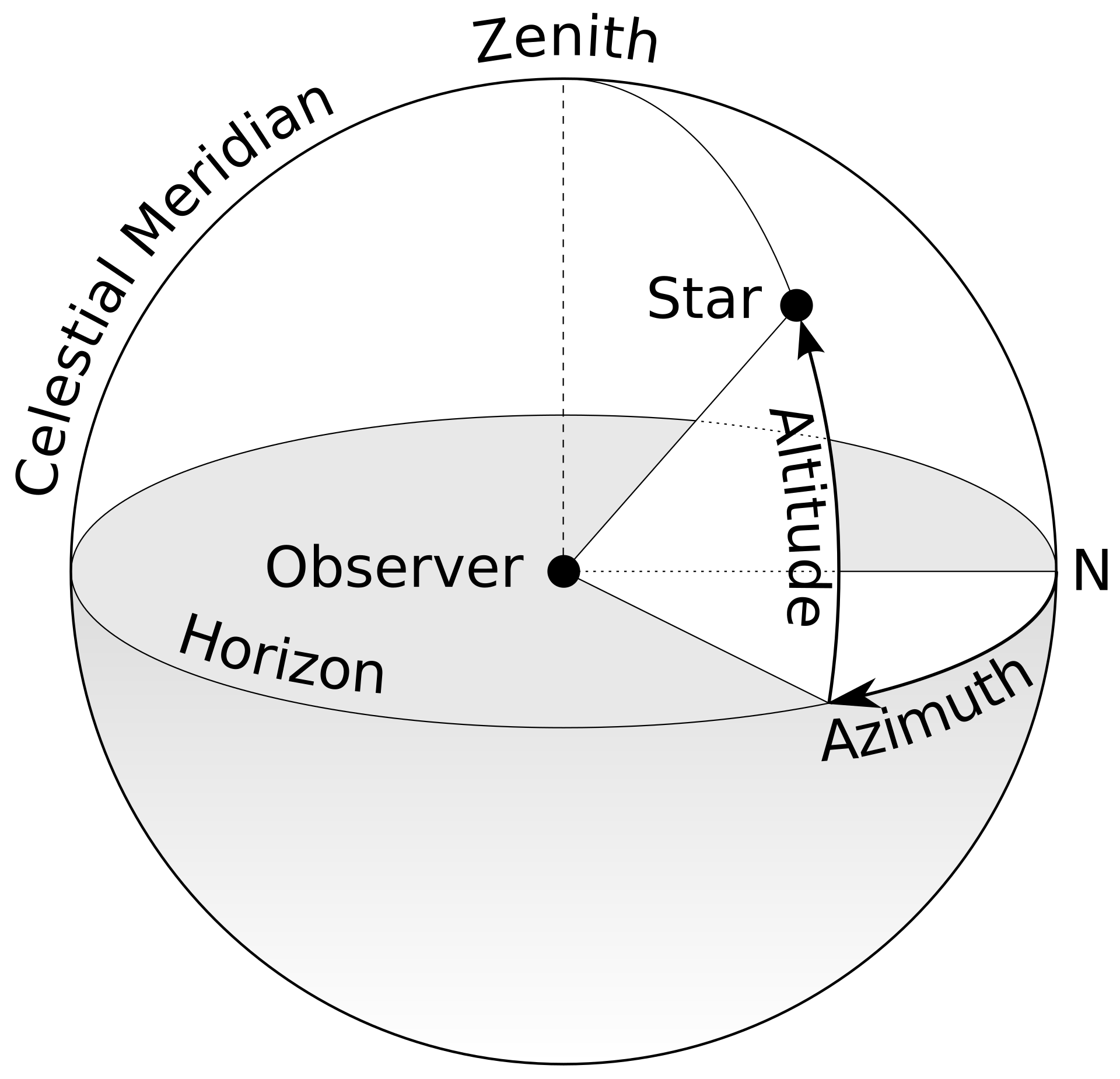
This is the system we ultimately will use to find our target in the sky. Horizontal coordinates use an azimuth, the direction of a celestial object from the observer, and an altitude to describe the position of a target. The azimuth is the right-hand angle offset from the target to true North. The altitude is the angle at which the target is in relation to the horizon, where the position directly overhead (the zenith point) is 90°. Because this system is oriented in relation to a Northward position, it can easily be calibrated about the North Star, Polaris. It is also important that the system is level to the horizon as well so the altitude is consistent.
Equatorial Coordinates
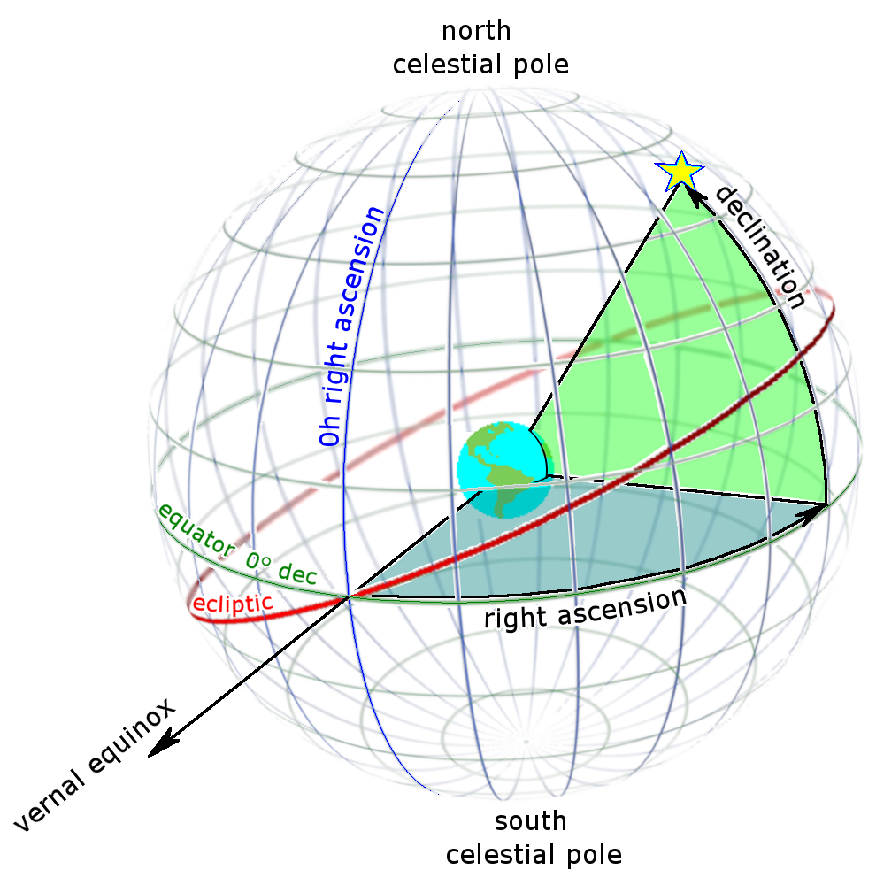
The equatorial coordinate system is a fixed coordinate system meaning the coordinates don't change as time progresses. Equatorial coordinates consist of an angle of declination and an angle of right ascension. Declination is simply the angle of the target from the Earth's equator. Right ascension is the angle between the vernal equinox point and the target. Although the angle of right ascension remains fixed, as Earth rotates, this angle is perceived to be different. We overcome this problem by using the local sidereal time. By subtracting the angle of right ascension from the local sidereal time (in degrees), we arrive at an hour angle which we can use to locate the target at the current local sidereal time. This is a little complicated, but due to the nature of this fixed coordinate system, it allows us to have coordinates pre-programmed which we can then convert to usable horizontal coordinates based on the GPS location and current time.
If you would like to read more on these systems and possibly get a better explanation, check out this article on converting right ascension and declination to altitude and azimuth. You can also read this Wikipedia page on celestial coordinate systems.
Materials
Hardware
- Micro USB Cable
- RobotZero (includes 9-axis sensor on board)
- GPS TinyShield
- 2 x Stepper Motors
Miscellaneous tools
- Basic soldering tools (Insulated wire, solder) - for lengthening motor cables
- 9 x M3 bolts (short)
- 3 x M4 bolts (long)
- 4 x M3 nuts
- High power laser pointer
- A mount for the system - 3D print files
- A level
Software
Hardware Assembly
Stack the GPS TinyShield on top of the RobotZero using the 32-pin connector. The onboard 9-axis sensor on the RobotZero will be used to get pitch and heading readings.
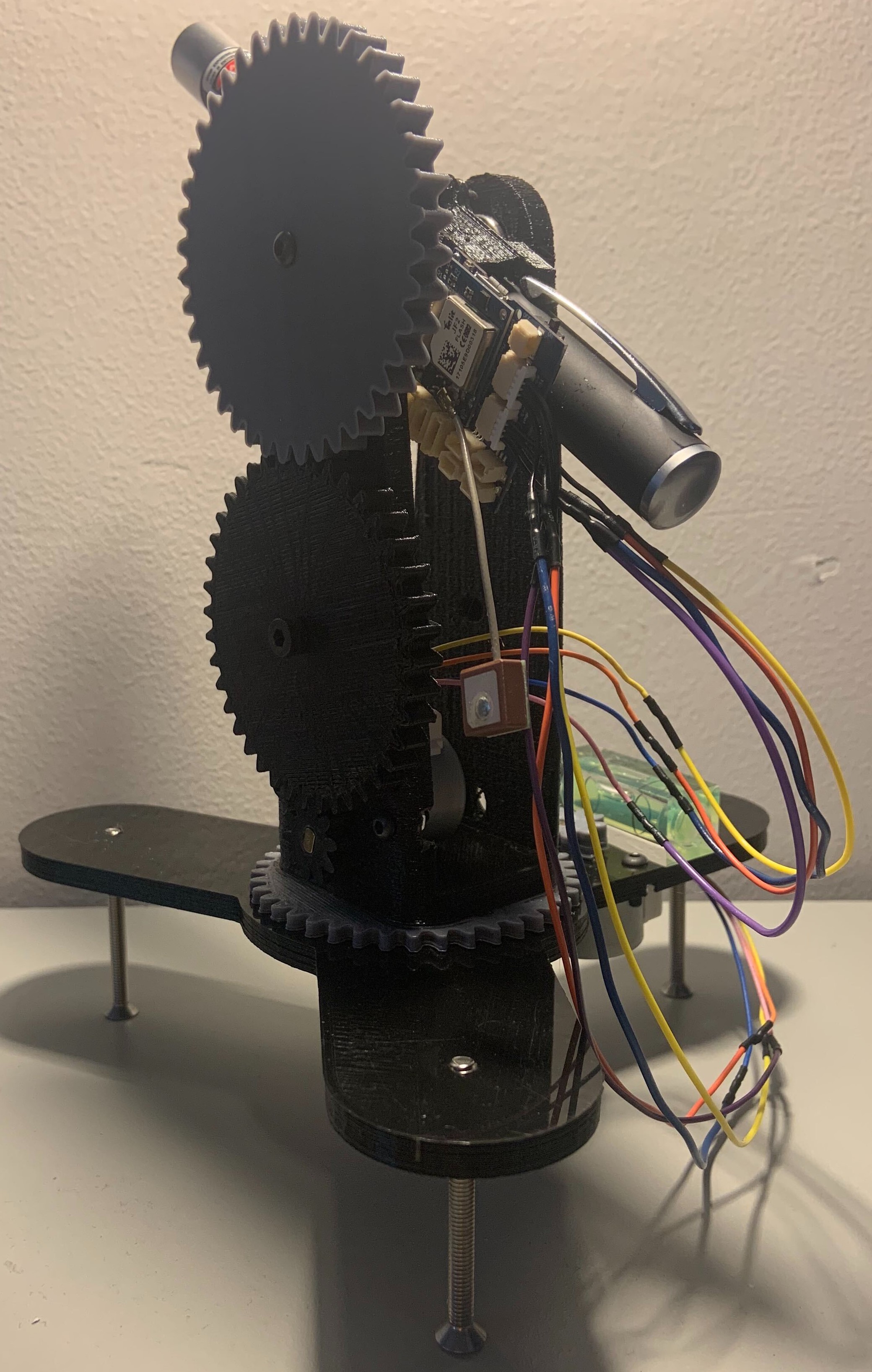
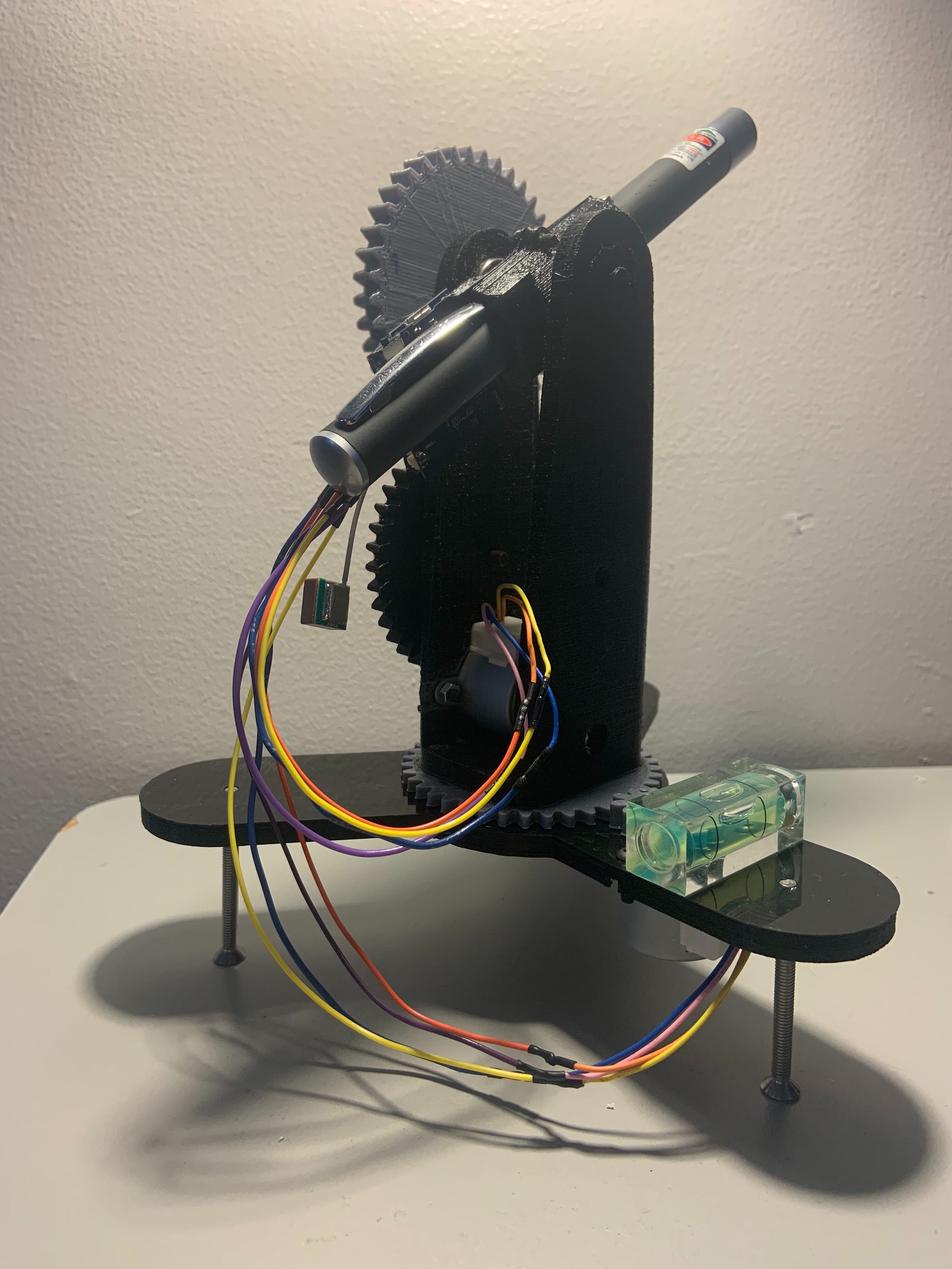
A mount is needed to hold and adjust the laser altitude and azimuth after the system is calibrated. STL files are available for the mount shown here, however the materials you have available to you may change how you go about this step. The code will function so long as your mount has a means of adjusting the altitude and azimuth of the laser. There is a tolerance for both altitude and azimuth which you can adjust in the code if your hardware mount is more crudely constructed. Be mindful that changing the setup may result in a need to change motor direction within the goToAzimuth and goToAltitude functions.
Note the positioning of the RobotZero on our mount. This is important for the 9-axis readings being used by the system, so you should orient your RobotZero in the same fashion in relation to your laser.
Notes on the Laser/Hardware Mount
- the laser mount is designed such that two M3 bolts can thread directly into the holes on the side and grip a 15mm diameter laser
- the laser mount is designed such that two M1 bolts (the bolts featured in the TinyDuino Mounting Kit) can thread directly into the mount to hold the RoborZero processor in place
- the bolt holding the top gear to the laser mount should be tightened so the rotation of the gear caused by driving the declination motor will cause the pitch of the laser to change
- both motors are secured by two M3 bolts and two M3 nuts each
- longer M4 bolts are to be used on the base so they can be adjusted to level the system
- due to the size of the system, the motor cables will have to be extended so they're able to reach the procesor board
Software Setup
The GPS module will automatically get the latitude, longitude, and UTC time needed for the functionality of this project. However, if you know where you are setting up the system and would like to have a manual input of this data at startup, the system will still function as long as these values are accurate. This means this project can still be built without a GPS TinyShield, but it will require a little more additional programming and setup time.
Upload Program
Plug in the micro USB cable from your computer to the RobotZero. Make the appropriate tools selections in the Arduino IDE and upload the program to the RobotZero.
Code
/*
  Created by Hunter Hykes for TinyCircuits 08/03/2020
  Working with GPS and RTC to get Local Sidereal Time (LST) dependent
  on the longitude of the device. Conveniently, the GPS timestamp is
  used to initialize the RTC.
  This program will use the positioning of the device on the Earth's
  surface along with the LST to determine the position of a given
  star or planet using the Equatorial Coordinate System (Right Ascension, Declination).
  https://en.wikipedia.org/wiki/Celestial_coordinate_system#Equatorial_system
  - In this system, Declination measures the angle between the celestial
    equator and the object observed, where the North Pole is 90deg and
    the South Pole is -90deg.
    - This positioning will be handled by the arm being able to rotate
      up to 90 degrees
  - Right Ascension is similar to longitude. It gives us the angle at
    which the object exists in relation to the Vernal Equinox Point.
    (360deg/24hrs ==> 1hr of Right Ascension is 15deg)
    - This positioning will be handled by the base being able to rotate
      a full 360 degrees
  - The Declination and Right Ascension (Equatorial Coordinates) will be
    converted to Altitude and Azimuth angles (Altazimuth Coordinates)
    since this system is easily calibreated around the North Star, Polaris
  To operate, point the laser at the North Star (Polaris) before powering
  the system on. The system has these coordinates stored for initialization
  and will use Polaris as a reference point by which it can interpret future
  9-axis readings from. Once the laser is aligned, open the Serial Monitor
  and the calibration will be finalized.
  MENU NOTES: Be sure to have "No line ending" selected in the serial monitor.
  Useful Resources:
    Converting RA and DEC to ALT and AZ                   http://www.stargazing.net/kepler/altaz.html
    RA & DEC Conversion from HH:MM:SS to Degrees          https://www.swift.psu.edu/secure/toop/convert.htm
    Altitude & Azimuth: The Horizontal Coordinate System  https://www.timeanddate.com/astronomy/horizontal-coordinate-system.html
  References Used:
    Star Track - Arduino Powered Star Pointer and Tracker https://www.instructables.com/id/Star-Track-Arduino-Powered-Star-Pointer-and-Tracke/
    Arduino Star-Finder for Telescopes                    https://www.instructables.com/id/Arduino-Star-Finder-for-Telescopes/
*/

#include "GPS.h"
#include <TinyGPS.h>
#include <RTCZero.h>
#include <Wire.h>           // For I2C connection
#include <Wireling.h>       // For Wireling Interfacing
#include <MotorDriver.h>    // Download latest here: https://github.com/TinyCircuits/TinyCircuits-TinyShield_Motor_Library/archive/master.zip
#include "RTIMUSettings.h"  // For the communication with the LSM9DS1
#include "RTIMU.h"
#include "RTFusionRTQF.h"
#include "CalLib.h"

#if defined (ARDUINO_ARCH_AVR)
#define SerialMonitorInterface Serial
#include <SoftwareSerial.h>
#elif defined(ARDUINO_ARCH_SAMD)
#define SerialMonitorInterface SerialUSB
#include "SoftwareSerialZero.h"
#endif

#define SERIAL_PORT_SPEED 115200

#define IMU_PORT 0    // this is the 9-Axis port
#define BUTTON_PIN A3 // this is the calibration button pin

// Simple templated averaging class based on Running Average by Rob Tillaart: http://arduino.cc/playground/Main/RunningAverage
template <const unsigned int N>
class RunningAverageFloat {
  public:
    void addValue(float val) {
      _ar[_index] = val;
      _index++;
      if (_index == N) _index = 0;
    };
    void fillValue(float val) {
      for (unsigned int i = 0; i < N; i++)_ar[i] = val;
    };
    float getAverage() {
      float sum = 0.0;
      for (unsigned int i = 0; i < N; i++)sum += _ar[i];
      return sum / (float)N;
    };
  protected:
    int _index = 0;
    float _ar[N];
};

#define NUM_SAMPLES 10
RunningAverageFloat<NUM_SAMPLES> headingAverage;
RunningAverageFloat<NUM_SAMPLES> pitchAverage;
RunningAverageFloat<NUM_SAMPLES> rollAverage;

TinyGPS gps; // create a gps object
RTCZero rtc; // create an rtc object

// The GPS connection is attached with a software serial port
SoftwareSerial softSerial(GPS_RXPin, GPS_TXPin);
#define Gps_serial softSerial


/* * * * * * * * * * * * * Target Coordinate Structure * * * * * * * * * * * * */
typedef struct {
  String name; // name of the target

  double DEC_degrees, DEC_arcmin, DEC_arcsec;
  double RA_hour, RA_min, RA_sec;

  double DEC_decimal, RA_decimal;   // declination and right ascension
  double HA_decimal;
  double ALT_decimal, AZM_decimal;  // altitude and azimuth
}target;

/* * * * * * * * * * * * * * * * * * * * * * * * Targets * * * * * * * * * * * * * * * * * * * * * * * * * * */
// initialize Polaris to DEC = 89* 15' 50.78" and RA = 2h 31m 48.704s
target Polaris = {"Polaris", 89, 15, 50.78, 2, 31, 48.704};           // (Ursa Minor)
// call updateCoords(Polaris); in setup to update all coordinates

// initialize Antares to DEC = -26* 25' 55.20" and RA = 16h 29m 24s
target Antares = {"Antares", -26, 25, 55.20, 16, 29, 24};             // (Scorpio)
// initialize Arcturus to DEC = 19* 10' 56.67" and RA = 14h 15m 39s
target Arcturus = {"Arcturus", 19, 10, 56.67, 14, 15, 39};            // (Bootes)
// initialize Betelgeuse to DEC = 7* 24' 25.43" and RA = 5h 55m 10s
target Betelgeuse = {"Betelgeuse", 7, 24, 25.43, 5, 55, 10};          // (Orion)
// initialize Regulus to DEC = 11* 58' 1.95" and RA = 10h 8m 22s
target Regulus = {"Regulus", 11, 58, 1.95, 10, 8, 22};                // (Leo)
// initialize Spica to DEC = -11* 9' 40.76" and RA = 13h 25m 11s
target Spica = {"Spica", -11, 9, 40.76, 13, 25, 11};                  // (Virgo)

/* * * * * * * * * * * * * * * Summer Triangle * * * * * * * * * * * * * * */
// initialize Altair to DEC = 8* 52' 5.96" and RA = 19h 50m 46s
target Altair = {"Altair", 8, 52, 5.96, 19, 50, 46};                  // (Aquilla)
// initialize Deneb to DEC = 45* 16' 49.22" and RA = 20h 41m 25s
target Deneb = {"Deneb", 45, 16, 49.22, 20, 41, 25};                  // (Cygnus)
// initialize Vega to DEC = 38* 47' 1.29" and RA = 18h 36m 56s
target Vega = {"Vega", 38, 47, 1.29, 18, 36, 56};                     // (Lyra)
/* * * * * * * * * * * * * * * * * * * * * * * * * * * * * * * * * * * * * * * * * * * * * * * * * * * * * * */

// initialize Andromeda Galaxy to DEC = 41* 16' 8.76" and RA = 0h 42m 44s
target Andromeda_G = {"Andromeda Galaxy", 41, 16, 8.76, 0, 42, 44};   // (near the Andromeda constellation)

// array of predefined targets
target predefined[10] = {Polaris, Antares, Arcturus, Betelgeuse, Regulus, Spica, Altair, Deneb, Vega, Andromeda_G};

/* * * * * * * * * * * * * * * Coordinate Input * * * * * * * * * * * * * * * */
target input = {"Input"}; // variable to store input data from recvdata()
target currentTarget;     // use this to set the current target


/* * * * * * * * * * * * * * * GPS and Time Stuff * * * * * * * * * * * * * * */
// your approximate latutude and longtitude (the GPS will update this anyways)
float gpslat = 41.08;
float gpslon = -81.517849;
int gpsyear;
byte gpsmonth, gpsday, gpshour, gpsminute, gpssecond, hundredths;
unsigned long age;
double timenow;

// Local Sidereal Time variables
double LST_degrees; // variable to store local side real time(LST) in degrees.
double LST_hours;   // variable to store local side real time(LST) in decimal hours.
double LST_minutes;
double LST_seconds;


/* * * * * * * * * * * * * * * 9-Axis Stuff * * * * * * * * * * * * * * */
#define DECLINATION -8.36
int aX, aY, aZ, gX, gY, gZ, mX, mY, mZ, tempF; // 9-Axis variables
float g_heading, g_pitch, g_roll;
float h_offset, p_offset;
float h_tolerance(2), p_tolerance(2); // Heading and pitch tolerances allowed. Set both to 2.

RTIMU *imu;                         // the IMU object
RTFusionRTQF fusion;                // the fusion object (for fused IMU readings)
RTIMUSettings settings;             // the settings object
CALLIB_DATA calData;                // the calibration data
int DISPLAY_INTERVAL = 200;         // interval between pose displays

// Global variables to retrieve, store, and schedule readings from the sensor
unsigned long lastDisplay;
unsigned long lastRate;
int sampleCount;
RTVector3 accelData;
RTVector3 gyroData;
RTVector3 compassData;
RTVector3 fusionData;

void setup() {
  /* * * * * * * * * * * * * * * * * * * * * * * * * * GPS Stuff * * * * * * * * * * * * * * * * * * * * * * * * * */
  Gps_serial.begin(GPSBaud);
  SerialMonitorInterface.begin(SERIAL_PORT_SPEED);

  gpsInitPins();
  delay(100);
  SerialMonitorInterface.print("Attempting to wake GPS module.. ");
  gpsOn();
  SerialMonitorInterface.println("done.");
  delay(200);

  gps.f_get_position(&gpslat, &gpslon); // Reads current latitude and longitude
  while ((gpslat == 1000) || (gpslon == 1000)) { // 1000 is the value that the tinyGPS library produces if no GPS signal is detected.
    gps.f_get_position(&gpslat, &gpslon); // This while loop will wait until the GPS acquires a signal.
    SerialMonitorInterface.println("*NO GPS SIGNAL*\n");
    smartdelay(1000);
  }
  // gpslat = (gpslat / 360) * (2 * PI); // Degrees to radians conversion.
  gps.crack_datetime(&gpsyear, &gpsmonth, &gpsday, &gpshour, &gpsminute, &gpssecond, &hundredths, &age); //Reads time and date from the GPS unit.
  timenow = ((double)gpshour + ((((double)gpssecond / 60.0) + (double)gpsminute) / 60.0)); // Merges hours, minutes and seconds.


  /* * * * * * * * * * * * * * * * * * * * * * * * * * RTC Stuff * * * * * * * * * * * * * * * * * * * * * * * * */
  rtc.begin(); // initialize RTC

  // Set RTC time and date based on GPS readings
  rtc.setTime(gpshour, gpsminute, gpssecond);
  rtc.setDate(gpsday, gpsmonth, (byte)(gpsyear - 2000));

  LST_time(); // may as well get a relatively recent LST here


  /* * * * * * * * * * * * * * * * * * * * * * * * * * 9-Axis Stuff * * * * * * * * * * * * * * * * * * * * * * */
  Wire.begin();       // Begin I2C communication
  Wireling.begin();
  setup9Axis();       // Initialize IMU
  delay(100);

  getOffset(Polaris); // get the initial offset between the Horizontal coordinates and the 9-axis readings


  /* * * * * * * * * * * * * * * * * * * * * * * * * * Motor Stuff * * * * * * * * * * * * * * * * * * * * * * */
  stepperInit(); // Initialize stepper motor driver
  /*
    Note: Motor 1 will be used to adjust azimuth (heading) and
          Motor 2 will be used to adjust altitude (pitch).
  */
}

void loop() {
  // These must be called every loop to update the Local Sidereal Time as time progresses
  // and then update the coordinates of the target resultant of the LST update.
  //LST_time();             // calculate Local Sidereal Time
  //updateCoords(Antares);  // update the coordinates of the target

  // print_GPS();
  // print_LST();
  //printTarget(Antares);

  get9Axis();
  //mtest(); // motor test
  //print9AxisAvg();

  //recvdata();
  goToTarget(Antares);

  delay(200);

  //menu(currentTarget);
}

void mtest() {
  setMotorCurrent(100);

  // increase heading
  setMotor(1, 10);
  delay(100);

  // we're relatively on-target
  setMotorCurrent(1); // stop moving
  setMotor(1, 0);
}

// this needs some real work
void menu(target &t) {
  SerialMonitorInterface.println(" - - - - - - - - - - - - - - - - - - - - - - - - - - - - - ");
  SerialMonitorInterface.println("|                  STAR POINTER MAIN MENU                  |");
  SerialMonitorInterface.println(" - - - - - - - - - - - - - - - - - - - - - - - - - - - - - ");

  SerialMonitorInterface.println(" 0) Enter Coordinates\n 1) Go To Predefined Star\n 2) Calibrate\n 3) Print GPS\n 4) Print LST\n 5) Print IMU");
  SerialMonitorInterface.flush();

  while(!SerialMonitorInterface.available()); // wait until something is entered

  switch(SerialMonitorInterface.read()) {
    case '0':
      SerialMonitorInterface.println("Enter in decimal format: <Right Ascension>, <Declination>");
      recvdata();
      break;
    case '1':
      listTargets(t);

      SerialMonitorInterface.println("Going to " + t.name + "...");
      printTarget(currentTarget);

      //goToTarget(Antares);
      break;
    case '2':
      SerialMonitorInterface.println("Align the laser on Polaris");
      getOffset(Polaris);
      break;
    case '3':
      print_GPS();
      break;
    case '4':
      LST_time();             // calculate Local Sidereal Time
      print_LST();
      break;
    case '5':
      get9Axis();
      //print9AxisAvg();
      break;
    default:
      break;
    }

    SerialMonitorInterface.flush();
    delay(500);
}

void listTargets(target &t) {
  SerialMonitorInterface.println();
  SerialMonitorInterface.println(" - - - - - - - - - - - - - - - - - - - - - - - - - - - - - ");
  SerialMonitorInterface.println("|         Select a target from the following list:         |");
  SerialMonitorInterface.println(" - - - - - - - - - - - - - - - - - - - - - - - - - - - - - ");

  // print out a list of the predefined stars
  for(int i = 0; i < 10; i++) {
    SerialMonitorInterface.print("|\t");
    print2digits(i);
    SerialMonitorInterface.println(") " + predefined[i].name);
  }
  SerialMonitorInterface.println(" - - - - - - - - - - - - - - - - - - - - - - - - - - - - - ");
  SerialMonitorInterface.println();

  while(!SerialMonitorInterface.available()); // wait until something is entered

  // get the user's selection from the list
  int sel = (int)SerialMonitorInterface.read() - '0';

  // set the current target based on the selection entered
  if(sel >= 0 && sel < 10) {
    t = predefined[sel];
    updateCoords(t);
  } else {
    SerialMonitorInterface.println("ERROR: Invalid selection. Returniung to Main Menu");
  }
}

// print UTC date and time; print latitude and longitude from GPS module
void print_GPS() {
  SerialMonitorInterface.println();

  SerialMonitorInterface.print("Lat: " + String(gpslat));
  SerialMonitorInterface.println("\tLon: " + String(gpslon));

  print_UTC_time();
  print_UTC_date();
}

void print_UTC_time() {
  SerialMonitorInterface.println();

  SerialMonitorInterface.print("UTC: ");

  print2digits(rtc.getHours());
  SerialMonitorInterface.print(":");
  print2digits(rtc.getMinutes());
  SerialMonitorInterface.print(":");
  print2digits(rtc.getSeconds());
}

void print_UTC_date() {
  SerialMonitorInterface.print("\t");

  print2digits(rtc.getDay());
  SerialMonitorInterface.print("/");
  print2digits(rtc.getMonth());
  SerialMonitorInterface.print("/");
  print2digits(rtc.getYear());
  SerialMonitorInterface.print(" ");

  SerialMonitorInterface.println();
}

// print the Local Sidereal Time
void print_LST() {
  SerialMonitorInterface.println();

  SerialMonitorInterface.print("LST: ");
  SerialMonitorInterface.print(LST_degrees);
  SerialMonitorInterface.println("\t(" + String((int)floor(LST_hours)) + "h " + String((int)floor(LST_minutes)) + "m " + String(round(LST_seconds)) + "s)");
}

void LST_time() {
  // Calculates local sidereal time based on this calculation,
  // http://www.stargazing.net/kepler/altaz.html

  // get dates from RTC, which has been initialized by the GPS module
  double M  = (double) rtc.getMonth();
  double Y  = (double) rtc.getYear();
  double D  = (double) rtc.getDay();
  double MN = (double) rtc.getMinutes();
  double H  = (double) rtc.getHours();
  double S  = (double) rtc.getSeconds();
  double A  = (double)(Y - 2000) * 365.242199;  // days since Jan 1 2000 to beginning of the year
  double B  = (double)(M - 1) * 30.4368499;     // days since the beginning of the year


    int Amo[12] = {0, 31, 59, 90, 120, 151, 181, 212, 243, 273, 304, 334};
    double B_2020 = 7303.5; // days since J2000 to beginning of 2020
    double JDN2000;

    if(((int)Y / 4) && (M > 2)) { // if it's a leap year and past the end of February (leap day)
      JDN2000 = Amo[rtc.getMonth() - 1] + 1 + B_2020 + D + (H/24.0);
      //JDN2000 = Amo[rtc.getMonth() - 1] + 1 + B_2020 + D-1 + (H/24.0);
    } else {  // if it's not a leap year, don't add the extra day
      JDN2000 = Amo[rtc.getMonth() - 1] + B_2020 + D + (H/24.0);
      //JDN2000 = Amo[rtc.getMonth() - 1] + 1 + B_2020 + D-1 + (H/24.0);
    }


  //double JDN2000 = A + B + (D - 1) + H/24.0;
  double decimal_time = H + (MN/60) + (S/3600); // this is our UT (Universal Time) value
  double LST = 100.46 + 0.985647 * JDN2000 + gpslon + 15 * decimal_time; // partial step to get LST in degrees
  LST_degrees = (LST - (floor(LST/360) * 360)); // LST in degrees
  LST_hours = LST_degrees/15; // LST in hours
  LST_minutes = (LST_hours - floor(LST_hours)) * 60;
  LST_seconds = (LST_minutes - floor(LST_minutes)) * 60;
}

// We need to use the Hour Angle in place of the Right Ascension based on
// what time it is. We can use our LST_hours for this.
void HourAngle(target &t) {
  t.HA_decimal = LST_degrees - t.RA_decimal;
}

// converts Right Ascension from HH:MM:SS to degrees
double HrMinSec_to_Deg(int h, int m, double s) {
  return 15 * (h + ((double)m/60.0) + ((double)s/3600.0));
}

// converts Declination from degrees, arcminutes, and arcseconds to decimal degrees
double DegArcminArcsec_to_Deg(int d, int am, double as) {
  return (d + ((double)am/60.0) + ((double)as/3600.0));
}

// converts Declination from decimal degrees to degrees, arcminutes, and arcseconds
void deg_to_DegArcminArcsec(target &t) {
  t.DEC_degrees = floor(t.DEC_decimal); // DEC in hours
  t.DEC_arcmin = (t.DEC_decimal - t.DEC_degrees) * 60;
  t.DEC_arcsec = (t.DEC_arcmin - floor(t.DEC_arcmin)) * 60;

  t.DEC_arcmin = floor(t.DEC_arcmin);

  // this isn't quite exact, but it's very, very close
}

// converts Right Ascension from HH:MM:SS to decimal degrees
void setDecimalCoords(target &t) {
  t.DEC_decimal = t.DEC_degrees + (t.DEC_arcmin/60.0) + (t.DEC_arcsec/3600.0);
  t.RA_decimal =  15 * (t.RA_hour + (t.RA_min/60.0) + (t.RA_sec/3600.0));
}

// converts Right Ascension from decimal degrees to HH:MM:SS
void deg_to_HrMinSec(target &t) {
  t.RA_hour = floor(t.RA_decimal/15.0); // RA in hours
  t.RA_min = ((t.RA_decimal/15.0) - t.RA_hour) * 60;
  t.RA_sec = (t.RA_min - floor(t.RA_min)) * 60;

  t.RA_min = floor(t.RA_min);

  // this isn't quite exact, but it's very, very close
}

// Converts the target's Equatorial Coordinates to Altazimuth Coordinates given
// the current Local Sidereal Time and update the variables in the target object.
void setAltazimuthCoords(target &t) {
  float DEG2RAD = 71.0/4068.0; // value used to convert degrees to radians
  float RAD2DEG = 4068.0/71.0; // value used to convert radians to degrees

  double sin_DEC = sin(t.DEC_decimal * DEG2RAD);
  double cos_DEC = cos(t.DEC_decimal * DEG2RAD);

  double sin_LAT = sin(gpslat * DEG2RAD);
  double cos_LAT = cos(gpslat * DEG2RAD);

  LST_time();   // update LST for the most accurate calculation of Horizontal coordinates
  HourAngle(t); // this needs updated constantly, so we update it before deciding on an Altazimuth coord at that second
  double sin_HA = sin(t.HA_decimal * DEG2RAD);
  double cos_HA = cos(t.HA_decimal * DEG2RAD);

  // formulas from http://www.stargazing.net/kepler/altaz.html#twig04a
  t.ALT_decimal = asin( sin_DEC*sin_LAT + cos_DEC*cos_LAT*cos_HA );

  double sin_ALT = sin((float)t.ALT_decimal);
  double cos_ALT = cos((float)t.ALT_decimal);

  t.ALT_decimal *= RAD2DEG; // convert ALT back to degrees

  t.AZM_decimal = acos( (sin_DEC - sin_ALT*sin_LAT) / (cos_ALT*cos_LAT) ) * RAD2DEG;

  if(sin_HA > 0) {                          // if sin(HourAngle) is positive,
    t.AZM_decimal = 360.0 - t.AZM_decimal;  // then the Azimuth is 360 - (AZM)
  }                                         // otherwise, the Azimuth is AZM

  //Use to debug Altitude and Azimuth calculations
  //SerialMonitorInterface.print("ALT: ");
  //SerialMonitorInterface.println(t.ALT_decimal);
  //SerialMonitorInterface.print("AZM: ");
  //SerialMonitorInterface.println(t.AZM_decimal);
}

// update all coordinates for the target
void updateCoords(target &t) {
  setDecimalCoords(t);
  setAltazimuthCoords(t);
}

void printTarget(target &t) {
  SerialMonitorInterface.println();
  SerialMonitorInterface.println(" - - - - - - - - - - - - - - - - - - - - - - - - - - - - - ");

  SerialMonitorInterface.println("Target: " + t.name);

  SerialMonitorInterface.print(" RA: ");
  SerialMonitorInterface.print(t.RA_decimal);
  SerialMonitorInterface.println("\t(" + String(t.RA_hour) + "h " + String(t.RA_min) + "m " + String(t.RA_sec) + "s)");

  SerialMonitorInterface.print(" HA: ");
  SerialMonitorInterface.println(t.HA_decimal);

  SerialMonitorInterface.print("DEC: ");
  SerialMonitorInterface.print(t.DEC_decimal);
  SerialMonitorInterface.println("\t(" + String(t.DEC_degrees) + "* " + String(t.DEC_arcmin) + "' " + String(t.DEC_arcsec) + "\")");

  SerialMonitorInterface.println();

  SerialMonitorInterface.print("AZM: ");
  SerialMonitorInterface.println(t.AZM_decimal);

  SerialMonitorInterface.print("ALT: ");
  SerialMonitorInterface.println(t.ALT_decimal);

  SerialMonitorInterface.println();
}

void setup9Axis() {
  calLibRead(0, &calData);                           // pick up existing mag data if there

  calData.magValid = false;
  for (int i = 0; i < 3; i++) {
    calData.magMin[i] = 10000000;                    // init mag cal data
    calData.magMax[i] = -10000000;
  }

  imu = RTIMU::createIMU(&settings);                 // create the imu object
  imu->IMUInit();
  imu->setCalibrationMode(true);                     // make sure we get raw data
  SerialMonitorInterface.print("ArduinoIMU calibrating device ");
  SerialMonitorInterface.println(imu->IMUName());

  // Slerp power controls the fusion and can be between 0 and 1
  // 0 means that only gyros are used, 1 means that only accels/compass are used
  // In-between gives the fusion mix.
  fusion.setSlerpPower(0.02);

  // use of sensors in the fusion algorithm can be controlled here
  // change any of these to false to disable that sensor
  fusion.setGyroEnable(true);
  fusion.setAccelEnable(true);
  fusion.setCompassEnable(true);
}

void get9Axis() {
  boolean changed;
  RTVector3 mag;

  if (imu->IMURead()) {                                 // get the latest data
    fusion.newIMUData(imu->getGyro(), imu->getAccel(), imu->getCompass(), imu->getTimestamp());

//    changed = false;
//    mag = imu->getCompass();
//
//    for (int i = 0; i < 3; i++) {
//      if (mag.data(i) < calData.magMin[i]) {
//        calData.magMin[i] = mag.data(i);
//        changed = true;
//      }
//
//      if (mag.data(i) > calData.magMax[i]) {
//        calData.magMax[i] = mag.data(i);
//        changed = true;
//      }
//    }

    displayRollPitchYaw(fusion.getFusionPose());

//    if (changed) {
//      SerialMonitorInterface.println("-------");
//      SerialMonitorInterface.print("minX: "); SerialMonitorInterface.print(calData.magMin[0]);
//      SerialMonitorInterface.print(" maxX: "); SerialMonitorInterface.println(calData.magMax[0]);
//
//      SerialMonitorInterface.print("minY: "); SerialMonitorInterface.print(calData.magMin[1]);
//      SerialMonitorInterface.print(" maxY: "); SerialMonitorInterface.println(calData.magMax[1]);
//
//      SerialMonitorInterface.print("minZ: "); SerialMonitorInterface.print(calData.magMin[2]);
//      SerialMonitorInterface.print(" maxZ: "); SerialMonitorInterface.println(calData.magMax[2]);
//    }

  }
}

void displayRollPitchYaw(RTVector3 vec) {
  g_roll = vec.x() * RTMATH_RAD_TO_DEGREE;
  g_pitch = vec.y() * RTMATH_RAD_TO_DEGREE;
  g_heading = to360(vec.z() * RTMATH_RAD_TO_DEGREE); // yaw

  SerialMonitorInterface.print(" roll:"); SerialMonitorInterface.println(g_roll);
  SerialMonitorInterface.print(" pitch:"); SerialMonitorInterface.println(g_pitch);
  SerialMonitorInterface.print(" yaw:"); SerialMonitorInterface.println(g_heading);
  SerialMonitorInterface.println("- - - - - - - - - - - - - - - - - - - - - - - - -");
}

//void print9Axis() {
//  SerialUSB.print("Roll: "); SerialUSB.println(roll, 2);
//  SerialUSB.print("Pitch: "); SerialUSB.println(pitch, 2);
//  SerialUSB.print("Heading: "); SerialUSB.println(heading, 2);
//}

void print9AxisAvg() {
  SerialUSB.print("Roll: "); SerialUSB.println(rollAverage.getAverage(), 2);
  SerialUSB.print("Pitch: "); SerialUSB.println(pitchAverage.getAverage(), 2);
  SerialUSB.print("Heading: "); SerialUSB.println(headingAverage.getAverage(), 2);
}

// gets 9-Axis data, averages the readings, and gets the heading and pitch offsets based on the target specified
// Polaris should be used to calibrate this system, so just call getOffset(Polaris)
void getOffset(target t) {
  updateCoords(t);

  while(!SerialMonitorInterface) { // keep reading until SerialMonitorInterface is opened
    get9Axis();
  }

  h_offset = headingAverage.getAverage() - t.AZM_decimal; // get heading offset between the target Azimuth and the 9-axis reading
  p_offset = pitchAverage.getAverage() - t.ALT_decimal;   // get pitch offset between the target Altitude and the 9-axis reading

  printTarget(t);
  SerialMonitorInterface.println("Calibrated on target " + t.name + " with offset");
  SerialMonitorInterface.println("\tHeading: " + String(h_offset) + "\tPitch: " + String(p_offset));
  SerialMonitorInterface.println(" - - - - - - - - - - - - - - - - - - - - - - - - - - - - - ");
  delay(1000);
}

// gets 9-axis data and adjusts Motor 1 to point at the target's Azimuth
void goToAzimuth(target t) {
  // float curr_azm = to360(t.AZM_decimal + h_offset);
  float curr_azm = to360((fusion.getFusionPose().z() * RTMATH_RAD_TO_DEGREE) + h_offset);

  SerialMonitorInterface.println("Current AZM = " + String(curr_azm) + " = YAW: " + String(fusion.getFusionPose().z()) + " + H_OFF: " + String(h_offset));
  /*
  while (floor(curr_azm) > floor(headingAverage.getAverage()) + h_tolerance) {
    // decrease heading
    setMotor(1, 1);
    get9Axis();
  }

  while (floor(curr_azm) < floor(headingAverage.getAverage()) - h_tolerance) {
    // increase heading
    setMotor(1, -1);
    get9Axis();
  }

  // we're relatively on-target
  setMotorCurrent(1); // stop moving
  setMotor(1, 0);*/
}

// gets 9-axis data and adjusts Motor 2 to point at the target's Altitude
void goToAltitude(target t) {
  // float curr_alt = to360(t.ALT_decimal + p_offset);
  float curr_alt = (fusion.getFusionPose().y() + p_offset);

  SerialMonitorInterface.println("Current ALT = " + String(curr_alt) + " = PITCH: " + String(fusion.getFusionPose().y()) + " + P_OFF: " + String(p_offset));
  /*
  while(floor(curr_alt) > floor(pitchAverage.getAverage()) + p_tolerance) {
    // decrease pitch
    setMotor(2, -1);
    get9Axis();
  }

  while (floor(curr_alt) < floor(pitchAverage.getAverage()) - p_tolerance) {
    // increase pitch
    setMotor(2, 1);
    get9Axis();
  }

  // we're relatively on-target
  setMotorCurrent(1); // stop moving
  setMotor(2, 0);*/
}

// gets 9-axis data and adjusts both Azimuth and Altitude
void goToTarget(target t) {
  get9Axis();
  setMotorCurrent(50);

  goToAzimuth(t);
  goToAltitude(t);
}

// the following few functions are borrowed

void recvdata() {
  // recvdata() function from gocivici's Star Track project used as reference fot this project!
  // https://github.com/gocivici/Star-Track
  // https://www.instructables.com/id/Star-Track-Arduino-Powered-Star-Pointer-and-Tracke/

  // This function receives data from serial as (0.00, 0.00)
  // splits it to strings by the comma "," then converts them to doubles
  while(!SerialMonitorInterface.available()); // do nothing

    String a = SerialMonitorInterface.readString();
    String ra_in, dec_in;

    for (int i = 0; i < a.length(); i++) {
      if (a.substring(i, i+1) == ",") {
        ra_in = a.substring(0, i);
        dec_in = a.substring(i + 1);
        break;
      }
    }

    // update the input target with the received decimal values
    input.RA_decimal = ra_in.toDouble();
    input.DEC_decimal = dec_in.toDouble();

    // echo the received decimal values
    SerialMonitorInterface.println("Entered: (RA = " + String(input.RA_decimal) + ", DEC = " + String(input.DEC_decimal) + ")");

    // update the other coordinates for clarification
    deg_to_DegArcminArcsec(input);
    deg_to_HrMinSec(input);

    setAltazimuthCoords(input);
    printTarget(input);         // print the target info
}

static void smartdelay(unsigned long ms) { //Defines smartdelay
  unsigned long start = millis();
  do {
    while (softSerial.available())
      gps.encode(softSerial.read());
  } while (millis() - start < ms);
}

// converts ranges of [-180, 180] to [0, 360]
float to360(float e) {
  if(e < 0) {         // if e is negative,
    return 360.0 + e; // then return 360 - e
  } else {
    return e;
  }
}

void print2digits(int number) {
  if (number < 10) {
    SerialMonitorInterface.print("0"); // print a 0 before if the number is < than 10
  }
  SerialMonitorInterface.print(number);
}
This project is set up to be used alongside a laptop to interface with the system outdoors. After the program is uploaded, it is important to level the system such that the laser can point accurately. Once the system is leveled, plug the RobotZero into the laptop and align the laser onto the North Star, Polaris. After the laser is fixed on the North Star, open up the serial monitor. This will calibrate the system and the system can then locate a star given its coordinates by using the pitch and heading readings from the 9-axis sensor.
Downloads
Contact Us
If you have any questions or feedback, feel free to email us or make a post on our forum. Show us what you make by tagging @TinyCircuits on Instagram, Twitter, or Facebook so we can feature it.
Thanks for making with us!